
Overview — one idea, two scales
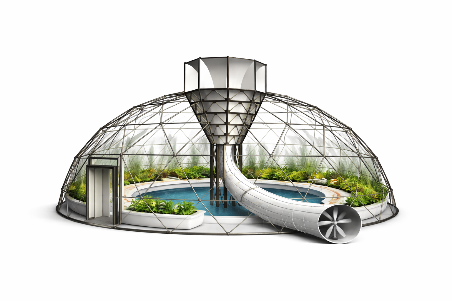
A geodesic dome that pulls water from air. Air enters a hexagonal top intake, is compressed down a vertical Venturi funnel, turns through a large-radius 90° curve into a horizontal duct holding inline turbines and an air-to-water heat exchanger, and is cooled below its dew point so water condenses, is treated, and stored. The turbine shaft drives a flywheel and generator; solar sits on the duct; inside is a pond and gardens.
🧊 See it in 3D
Interactive 3D models of the dome, the ducted AWG unit, the centre intake and the aquaponics rig — plus build recordings and concept renders — are in the Gallery (3D Models).That build estimate is broken down — with a live, editable budget tracker — on the Costs & Budget page.
Temporary by design
The Kudla property may be subdivided in 2–3 years, so the whole build is demountable: screw-pile / skid footings (no slab), a boltable frame, and the pond is a portable tank (no dug or lined hole). It can be packed down and the site fully restored. The teardown order + per-subsystem demount spec is on the Schedule.The honest framing
This is no longer "AI art" — the chats walked it from a rough concept to early-stage industrial design where every component is physically connected and logically arranged. But nothing is physically validated yet. The open question is whether the physics holds at all: "there's a chance I've spent ten years thinking about something completely ridiculous."Structure & geometry
| Element | Spec | Notes |
|---|---|---|
| Dome | 15 m Ø hemisphere | Transparent greenhouse-style membrane over a minimal segmented (geodesic) frame |
| Top intake | Hexagonal, 6 flat panels | Angled inward to form a funnel that captures airflow |
| Vertical funnel | Narrows on descent | Compresses airflow; should be taller + narrower at the throat than current renders show |
| Throat → curve | Large-radius 90° duct | Smooth, continuous, visible transition from vertical to horizontal |
| Horizontal duct | Cylindrical | Holds the turbines + heat exchanger; only slightly exits the dome wall |
| Base ring | Thick continuous circular ring | Integrated water storage + structure |
| Interior | Central pond + gardens | Pond with a fish; bench facing pond; electrical box parallel/tangent to the base ring |
Airflow path (locked)
images/dome-main-concept.pngTurbine & blade design
The system is closer to turbomachinery than to a backyard windmill — a ducted axial turbine inside a Venturi accelerator, with pressure staging, flywheel smoothing, AWG extraction and a diffuser. The duct straightens and accelerates the air, so blade choice is very specific.
Recommended rotor
- Type: twisted axial-flow, lift-based airfoil blades
- Blade count: 5–7 swept blades (range 5–9); high-solidity rotor (more, narrower blades than a normal wind turbine)
- Diameter in duct: fill 92–96% of the duct diameter
- Geometry: aggressive twist root→tip (because tip speed v = ωr grows with radius), airfoil section, narrower near the tip, moderate chord
- Material: carbon / composite
- Add-ons: stator vanes before the rotor + a diffuser cone after it; a short light helical pre-rotor to condition incoming flow
| Rank | Blade type | Why |
|---|---|---|
| Best | Axial airfoil (twisted) | Highest efficiency in fast ducted flow; quiet; scalable |
| 2nd | Mixed-flow / swept | Better pressure handling, less stall under compression |
| 3rd | Helical | Smoother torque, quieter, good at low RPM / turbulence |
| Avoid | Savonius | Drag-based, poor efficiency, bad in ducts |
| Avoid | Standard open-air HAWT | Tuned for free atmosphere, not confined accelerated flow |
| Avoid | Flat blades | Easy to build, terrible efficiency |
Tip clearance is critical
The gap between blade tip and duct wall is one of the biggest efficiency levers. Smaller gap → less vortex loss, higher pressure differential. In ducted turbines the duct itself (suction, mass-flow, reduced turbulence) can contribute almost as much as the rotor.Don't choke the flow
The turbine must be low-resistance — it recovers energy without strangling airflow. Over-restrict it and you kill the whole system. The turbine offsets fan/intake energy; it does not power the entire AWG.AWG cooling & condensation core
Atmospheric water generation is, fundamentally, an energy-intensive refrigeration process. Two cooling stages:
- Pre-cool — intake air through an underground earth-tube loop (~18 °C) or a heat exchanger on exhaust air, to cut compressor load.
- Active cool — a refrigeration coil drops air below dew point; water condenses on the coil and drips to a tray.
Rendered refrigeration rig (the labelled schematic)
| Spec | Value |
|---|---|
| Duct diameter | 750 mm |
| Duct length | 2.4 m |
| Evaporator stages | 4 × 600 mm, one helical finned coil each |
| Airflow core | 600 mm |
| Compressors | 4 independent units |
Refrigeration vs. desiccant
- Refrigeration (most practical): reverse-AC — scroll/rotary compressor (1–2 kW), big evaporator coil, condenser + fans, intake filters.
- Desiccant + solar regen (more off-grid): silica gel / lithium chloride absorbs moisture at night, solar heat releases it by day. Lower electrical load, better in dry air, more mechanically complex.
- Recommended direction: a hybrid — refrigeration core with a desiccant assist.
Inline air-to-water heat exchanger
8–10 very thin parallel pipes running vertically across the duct, evenly spaced, positioned between turbine 1 and turbine 2 — cooling the air without blocking most of the flow.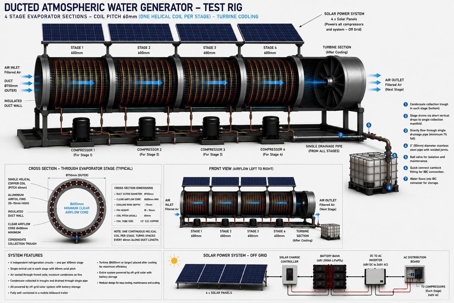
images/ducted-awg-detail.pngWater treatment & storage
- Tank: 1000 L target, food-grade poly or stainless, integrated in the dome base ring.
- Mineralisation stage matters — condensed water is essentially distilled and needs minerals added back for drinking.
- Optional pump to a pressure tank; overflow bypass to prevent flooding.
- Multi-stage intake filtration is mandatory — dust is a killer for the coils.
Hybrid water sources (more reliable overall)
Rather than pulling 100% from air: AWG + rainwater capture, AWG + fog-harvesting mesh, AWG + greywater recycling.
Drivetrain & power generation
- The flywheel is a solid circular disk mounted vertically at ground level — it smooths torque and stores rotational energy.
- Generated power runs fans, control systems and can assist (not replace) the compressor.
- Solar: 3 flat panels in a row on top of the external duct in the render (~400–450 W each).
Power demand vs. solar reality
| Load | Draw |
|---|---|
| Per compressor (0.5–0.75 HP) | 400–700 W |
| 4 compressors total | ~1.6–2.8 kW |
| Fans, pumps, controls, inverter loss | +200–800 W |
| Whole system, continuous | 2–4 kW |
| Daily energy @ 2–4 kW | 48–96 kWh/day |
| AWG efficiency | 0.3–0.5 kWh per litre |
The solar in the render is wildly insufficient
3–4 panels ≈ 1.6–1.8 kW peak ≈ only ~6–9 kWh/day usable in Adelaide, against a need of 40–90 kWh/day. Serious off-grid operation realistically needs 15–30 panels + a large battery bank. Energy — not airflow — is the limiting factor.Turbine output (6 m prototype)
| Wind | Output |
|---|---|
| Low (3 m/s) | 50–150 W |
| Moderate (5 m/s) | 200–600 W |
| High (8 m/s) | up to 1.5 kW |
Turbine output is far below compressor demand — it offsets fan energy, it doesn't run the system.
Water yield (the rendered rig)
| Conditions | RH | Estimated output |
|---|---|---|
| Hot dry day | 25–35% | 5–15 L/day |
| Average | 40–55% | 15–35 L/day |
| Humid / night | 65–85% | 35–70+ L/day |
This geometry actually outperforms typical small AWGs because of the large airflow volume, long evaporator path, multi-stage cooling and big condensation surface area. But yield is humidity-bound, and Adelaide is dry (summer ~30–60% RH). Run it at night when humidity is highest and ambient temperature lowest.
Efficiency moves & smart control
- Run mostly at night (higher humidity, cooler air).
- Earth-tube pre-cooling (~18 °C) + a solar-thermal updraft (chimney effect) to cut fan/compressor load.
- Variable-speed compressor matched to conditions; oversize coils for better condensation.
- Dew-point-targeting controller: temp + humidity + dew-point sensors; only run the compressor when RH > ~50%, use passive airflow first, boost with fans only when needed.
Where the concept is genuinely novel
Most AWGs ignore airflow dynamics and brute-force with compressors. The funnel + turbine pre-optimise airflow and recover energy — an estimated 20–40% energy saving vs. a standard AWG. That is the real claim. Not "free / passive water."6 m prototype spec (the deck's number)
| Component | Value |
|---|---|
| Dome diameter | 6 m |
| Height | 3 m |
| Funnel throat | 0.4 m |
| Duct diameter | 400 mm |
| Turbines | 3 inline |
Venturi ratio recommended 1.5:1 to 2.5:1. Intake funnel 2–4 m Ø tapering to a narrow throat. Airflow need for the 100 L/day target: roughly 500–1500 m³/hour (EC axial fans or centrifugal blowers if passive airflow is insufficient).
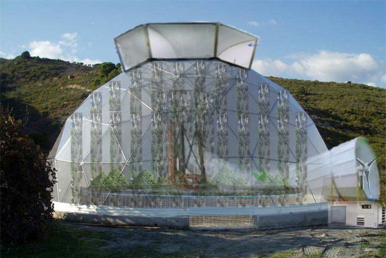
Master 3D render prompt (verbatim)
The locked design description used to generate the concept render — kept here exactly so the design intent is recoverable.
images/geodome-on-site.jpgOpen problems & unknowns
- Nothing is physically validated — does the physics hold at all?
- Funnel still not aggressive enough in renders — needs a taller drop and narrower throat for real compression.
- Compressor sizing per stage (0.5–0.75 HP est.) depends on refrigerant, condenser efficiency, evaporator + ambient temps.
- Exact solar count for off-grid (15–30 panels) depends on local solar resource + battery bank.
- Bevel-gear / turbine sizing not finalised.
- Reconcile the deck's optimistic "free water" framing with the energy reality (~20–40% savings, not 100% passive).
- No proper workshop — twisted airfoil blades + tight tip clearances are genuinely hard to make DIY, around containers and a truck body.
Reconstructed from the engineering chats in the archive. Numbers are estimates from those conversations, not measured results — the project is at concept/render stage. Source files: blades, coil length, Untitled Document 1, long conversation, Image Editing Request.